Ray Tracing vs Ray Marching
Two approaches to the same fundamental problem: finding what a ray hits
One of the goals of computer graphics is to synthesize images of virtual scenes simulating the behaviour of light. In order to determine the visible surfaces described in the environment and the respective color of each pixel displayed on the screen, two of the most widespread techniques are rasterization and Ray Tracing. Rasterization, widely used in real-time applications like video games, prioritizes speed and efficiency. In contrast, Ray Tracing, commonly employed in high-quality 3D animations, sacrifices speed for photorealistic accuracy by simulating the paths of individual light rays. Beyond these methods, Ray Marching offers a unique approach, particularly suited for rendering complex implicit surfaces and volumetric effects. In this chapter, we will focus on Ray Tracing and explore how it compares and contrasts with Ray Marching, shedding light on their respective strengths and applications.
Traversing the Canvas
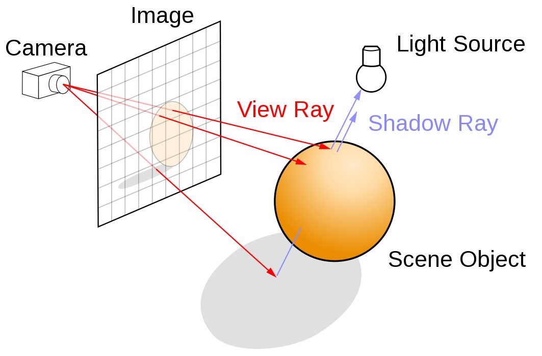
A scene consists of a camera, 3D objects, and light sources placed in the environment. The goal when using Ray Tracing or Ray Marching is to generate a 2D render of the scene from the camera's point of view. We will need to traverse the canvas, a 2D grid with the dimensions of our final image. Then, given a camera point, we iterate over each position in the canvas, shooting a ray in its direction. This process is the basis of both Ray Marching and Ray Tracing, as shown in Figure 2.
For didactic purposes, we will ignore details such as the field of view, and we will assume that the distance between the canvas and the camera origin is always equal to 1, and that the canvas center will be positioned at $(0, 0, 0)$. We then establish the following definitions:
- CanvasResolution — a 2D vector where each component represents the canvas' width and height.
- uv — a mapping of the canvas' coordinate system, offsetting the $(0, 0)$ coordinate to the canvas' center and ranging between -1 and 1. We later divide it by the resolution to fix the aspect ratio.
- RayOrigin — a 3D vector representing the viewer's position, initialized at $(0, 0, 1)$.
- RayDirection — a normalized 3D vector representing the ray shot from the origin towards the pixel's position.
- Hit — a data structure storing information about the ray's interaction with geometry, including hit position, surface normal, distance from the origin, and data for lighting calculations.
PROCEDURE Render(Canvas, Scene)
  FOR y = 0 TO CanvasResolution.y - 1
    FOR x = 0 TO CanvasResolution.x - 1
      uv ← ([x, y] - 0.5 × CanvasResolution) / CanvasResolution.y
      RayOrigin ← [0, 0, 1]
      RayDirection ← normalize([uv.x, uv.y, 0] - RayOrigin)
      Hit ← TraceRay(RayOrigin, RayDirection, Scene)
      IF Hit.isHit
        HitColor ← GetHitColor(Hit, RayDirection, Scene)
        SetPixelColor(x, y, HitColor)
      ELSE
        SetPixelColor(x, y, BACKGROUND_COLOR)
      END IF
    END FOR
  END FOR
END PROCEDURE
The pseudocode explicitly uses nested loops to traverse the canvas. In the
GLSL implementation below, the iteration logic is unnecessary because the
fragment shader operates on a per-pixel basis — each invocation of the
shader corresponds to a single pixel on the canvas, and the GPU
automatically handles the parallel execution. The input fragCoord provides the current pixel's coordinates.
void mainImage( out vec4 fragColor, in vec2 fragCoord )
{
    Scene scene = createScene();

    vec2 uv = (fragCoord - .5*iResolution.xy) / iResolution.y;
    vec3 color = vec3(0.);

    // Creating Ray
    vec3 rayOrigin = vec3(0., 0., 1.);
    vec3 rayDirection = normalize(vec3(uv.xy, 0.) - rayOrigin);
    Ray ray = Ray(rayOrigin, rayDirection);

    // Tracing Ray
    Hit hit = traceRay(ray, scene);

    if (hit.isHit) color = getHitColor(hit, ray, scene);

    // Output to screen
    fragColor = vec4(color,1.0);
}
Code 1: Canvas Traversal
Tracing the Ray
In ray tracing, once a ray is cast in the direction of a pixel on the canvas, it must traverse the scene to identify the closest object intersecting the ray. This requires a function capable of calculating the intersection between the ray and the geometric objects in the scene. The closest intersection point determines what will be rendered on the screen.
PROCEDURE TraceRay(RayOrigin, RayDirection, Scene)
  ClosestHit ← RAYHIT_INFINITY
  FOR EACH object IN Scene
    Hit ← RayObjectIntersection(object, RayOrigin, RayDirection)
    IF Hit.distance < ClosestHit.distance
      ClosestHit ← Hit
    END IF
  END FOR
  RETURN ClosestHit
END PROCEDURE
In traditional computer graphics, most objects on a screen are represented as a collection of triangles. This allows any geometry tessellated into triangles to be described using ray-triangle intersection calculations. However, rendering smooth shapes requires an extremely fine mesh, leading to a high polygon count — a significant performance bottleneck in scenes with thousands of objects.
In the following exmaple, the scene is simplified to a single sphere. Since
the analytic solution for ray-sphere intersection is well known, the surface
can be rendered smoothly and accurately without relying on geometric
tessellation. Our
GetHitColor function currently returns only the object's albedo —
the pure color of the object. The provided shader renders a scene with a black
background, a large white sphere below the camera to simulate the ground, and
a smaller red sphere above it.
#define SHADOW_BIAS 1.e-4

#define INF 3.402823466e+38
#define PI  3.1415926535898

#define NULL_MATERIAL Material(vec3(0.),0.,0.,false)
#define RAYHIT_INFINITY Hit(vec3(INF),vec3(0.),INF,NULL_MATERIAL,false)
#define LIGHT_SPHERE Sphere(light.pos,0.1,Material(light.color,0.,0.,false))

struct Ray{
    vec3 origin;
    vec3 direction;
};

struct Material{
    vec3 albedo;
    float specularPower;
    float specularIntensity;
    bool isLit;
};

struct Hit{
    vec3 point;
    vec3 normal;
    float dist;
    Material material;
    bool isHit;
};


struct Sphere{
    vec3 pos;
    float radius;
    Material material;
};

struct Light{
    vec3 pos;
    vec3 color;
    float intensity;
};

struct Scene{
    Sphere[2] spheres;
    Light light;
};

Scene createScene(){
       Material groundMaterial = Material(
        vec3(1.), // albedo
        150., // specular power
        0., // specular intensity
        true // is lit
    );


    Material sphereMaterial = Material(
        vec3(1.0, 0.0, 0.0), // albedo
        150., // specular power
        0.5, // specular intensity
        true // is lit
    );

    Sphere s1 = Sphere(
        vec3(0., 0., -5.),
        1.,
        sphereMaterial
    );

    Sphere ground = Sphere(
        vec3(2., -1001., -5.),
        1000.,
        groundMaterial
    );

    Sphere[2] spheres = Sphere[](s1, ground);

    Light light = Light(
        vec3(0. + cos(iTime)*2., 0.5, -5. + sin(iTime)*2.), // position
        vec3(1.), // color
        15. // intensity
    );


    Scene scene = Scene(spheres, light);
    return scene;
}

Hit raySphereIntersection(Sphere sphere, Ray ray){
    Hit hit = RAYHIT_INFINITY;

    vec3 ro = ray.origin;
    vec3 rd = ray.direction;
    vec3 s = sphere.pos;
    float R = sphere.radius;

    float t = dot(s - ro, rd);
    if(t < 0.) return hit;
    vec3 p = ro + rd * t;

    float y = length(s - p);
    if(y > R) return hit;
    float x = sqrt(R*R - y*y);

    float temp1 = t - x;
    float temp2 = t + x;
    float t1 = min(temp1, temp2);
    if (t1 < 0.) return hit;
    float dist = t1;

    hit.point = ro + rd * dist;
    hit.normal = normalize(hit.point - sphere.pos);
    hit.dist = dist;
    hit.material = sphere.material;
    hit.isHit = true;

    return hit;
}

Hit castRay(Ray ray, Scene scene){
    Hit closestHit = RAYHIT_INFINITY;

    for(int i = 0; i < 2; i++){
        Hit hit = raySphereIntersection(scene.spheres[i], ray);

        if(hit.dist < closestHit.dist) closestHit = hit;
    }

    return closestHit;
}

vec3 getLight(Hit hit, Ray ray, Scene scene)
{
    // Unlit material
    return hit.material.albedo;
}

void mainImage( out vec4 fragColor, in vec2 fragCoord )
{
    Scene scene = createScene();

    vec2 uv = (fragCoord - .5*iResolution.xy) / iResolution.y;
    vec3 color = vec3(0.);

    // Creating Ray
    vec3 rayOrigin = vec3(0., 0., 1.);
    vec3 rayDirection = normalize(vec3(uv.xy, 0.) - rayOrigin);
    Ray ray = Ray(rayOrigin, rayDirection);

    // Casting Ray
    Hit hit = castRay(ray, scene);

    if (hit.isHit) color = getLight(hit, ray, scene);

    // Output to screen
    fragColor = vec4(color,1.0);
}
Marching the Ray
If the term "trace" implies a fast, swift motion, "march" is used to convey
taking one step at a time. The Ray Marching algorithm uses the
MarchRay function instead of TraceRay — rather than
calculating a direct intersection, it iteratively marches through space, at each
step sampling the distance to all objects in the scene, until one distance turns
negative or smaller than a specified threshold (a hit). The distance-sampling
function is called SDF (Signed Distance Function), as it returns positive when
outside the object and negative when inside.
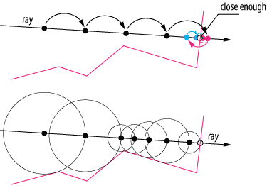
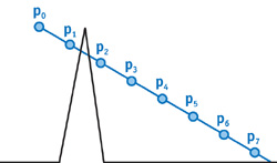
Ray Marching could be considered a family of algorithms. The most straightforward approach is to use a fixed step size, where the ray advances in uniform increments. While simple, this method has notable limitations: the ray may need to be backtracked to locate the precise point of intersection (Figure 4, top), and fixed steps risk skipping over fine details or thin structures entirely (Figure 5).
To prevent the march from ever skipping a surface between steps, the next step size can be picked as the minimum distance to any object in the scene — this is sphere tracing. The ray then acts as if it has a sensor, slowing down when surfaces are nearby. Each circle in Figure 4 (bottom) represents the safe step radius at that position.
PROCEDURE MarchRay(RayOrigin, RayDirection, Scene)
  MarchDistance ← 0
  Hit ← NULL_HIT
  IsHit ← false
  FOR step = 0 TO MAX_MARCH_STEPS - 1
    MarchPos ← RayOrigin + (MarchDistance × RayDirection)
    Hit ← GetDistance(MarchPos, Scene)
    IF Hit.distance < SURFACE_DISTANCE
      IsHit ← true
      BREAK
    END IF
    IF MarchDistance > MAX_MARCH_DISTANCE
      BREAK
    END IF
    MarchDistance ← MarchDistance + Hit.distance
  END FOR
  RETURN Hit
END PROCEDURE #define SHADOW_BIAS 1.e-4
#define MAX_MARCHING_STEPS 150
#define MAX_MARCHING_DISTANCE 40.
#define SURFACE_DISTANCE .0001
#define INF 3.402823466e+38
#define PI 3.1415926535898
#define NULL_MATERIAL Material(vec3(0.),0.,0.,false)
#define NULL_CANDIDATE HitCandidate(INF,NULL_MATERIAL);
#define RAYHIT_INFINITY Hit(vec3(INF),vec3(0.),INF,NULL_MATERIAL,false)
#define LIGHT_SPHERE Sphere(light.pos,0.1,Material(light.color,0.,0.,false))
struct Ray{
vec3 origin;
vec3 direction;
};
struct Material{
vec3 albedo;
float specularPower;
float specularIntensity;
bool isLit;
};
struct Hit{
vec3 point;
vec3 normal;
float dist;
Material material;
bool isHit;
};
struct Sphere{
vec3 pos;
float radius;
Material material;
};
struct Light{
vec3 pos;
vec3 color;
float intensity;
};
struct Scene{
Sphere[2] spheres;
Light light;
};
struct HitCandidate{
float dist;
Material material;
};
Scene createScene(){
Material groundMaterial = Material(
vec3(1.), // albedo
150., // specular power
0., // specular intensity
true // is lit
);
Material sphereMaterial = Material(
vec3(1.0, 0.0, 0.0), // albedo
150., // specular power
0.5, // specular intensity
true // is lit
);
Sphere s1 = Sphere(
vec3(0., 0., -5.),
1.,
sphereMaterial
);
Sphere ground = Sphere(
vec3(2., -1001., -5.),
1000.,
groundMaterial
);
Sphere[2] spheres = Sphere[](s1, ground);
Light light = Light(
vec3(0. + cos(iTime)*2., 0.5, -5. + sin(iTime)*2.), // position
vec3(1.), // color
15. // intensity
);
Scene scene = Scene(spheres, light);
return scene;
}
float sphereDistance(vec3 point, Sphere sphere){
return length(point- sphere.pos) - sphere.radius;
}
HitCandidate getDist(vec3 point, Scene scene){
HitCandidate minDist = NULL_CANDIDATE;
for(int i = 0; i < 2; i++){
float dist = sphereDistance(point, scene.spheres[i]);
if(dist < minDist.dist){
minDist.dist = dist;
minDist.material = scene.spheres[i].material;
}
}
// render sphere in point light's location
return minDist;
}
vec3 getNormal(vec3 point,float d, Scene scene){
vec2 e = vec2(.01, 0);
HitCandidate n1 = getDist(point - e.xyy, scene);
HitCandidate n2 = getDist(point - e.yxy, scene);
HitCandidate n3 = getDist(point - e.yyx, scene);
vec3 stretchedNormal = d-vec3(
n1.dist,
n2.dist,
n3.dist
);
return normalize(stretchedNormal);
}
Hit marchRay(Ray ray, Scene scene){
float distToCamera = 0.;
bool isHit = false;
vec3 marchPos = ray.origin;
HitCandidate nextStepHit = NULL_CANDIDATE;
for(int stp=0; stp<MAX_MARCHING_STEPS; stp++){
marchPos = ray.origin + (distToCamera * ray.direction);
nextStepHit = getDist(marchPos, scene);
distToCamera += nextStepHit.dist;
if(nextStepHit.dist < SURFACE_DISTANCE){
isHit = true;
break;
}
if(distToCamera > MAX_MARCHING_DISTANCE){
isHit = false;
break;
}
}
// generate Hit
Hit hit = Hit(
marchPos,
getNormal(marchPos,nextStepHit.dist, scene),
distToCamera,
nextStepHit.material,
isHit);
return hit;
}
vec3 getLight(Hit hit, Ray ray, Scene scene)
{
// Unlit material
return hit.material.albedo;
}
void mainImage( out vec4 fragColor, in vec2 fragCoord )
{
Scene scene = createScene();
vec2 uv = (fragCoord - .5*iResolution.xy) / iResolution.y;
vec3 color = vec3(0.);
// Creating Ray
vec3 rayOrigin = vec3(0., 0., 1.);
vec3 rayDirection = normalize(vec3(uv.xy, 0.) - rayOrigin);
Ray ray = Ray(rayOrigin, rayDirection);
// Marching Ray
Hit hit = marchRay(ray, scene);
if (hit.isHit) color = getLight(hit, ray, scene);
// Output to screen
fragColor = vec4(color,1.0);
}The shader above renderes the scene with a low step cap of 150 to illustrate a limitation of the method. Careful inspection reveals that the distant ground plane disappears near the edges of the sphere. This occurs because rays take smaller steps when approaching a surface, requiring more iterations to traverse its boundary. In practice, most rays terminate within fewer than 10 steps due to scene distance limits, and our final scenes use a cap of around 1000 steps.
When to march rather than trace
At first glance, Ray Tracing comes off as the best, most optimal method. Ray Marching is prone to visual artifacts and might take many marching steps, especially in crowded scenes. Most 3D modeling done in software like Blender2 and ZBrush3 is not based on primitives such as spheres and boxes, but rather on polygons. As such, any traditionally modeled scene with high poly counts, textures, reflection, refraction, and shadows is better suited to Ray Tracing, especially considering recent advances in hardware-accelerated path tracing on modern GPUs such as the NVIDIA RTX architecture [NVIDIA].
However, Ray Marching has competitive applications. The flexibility of SDFs, and capability of diverse object combination and manipulation, makes it particularly well-suited for rendering complex, mathematically defined shapes such as fractals. Moreover, Ray Marching excels at rendering volumetric effects like clouds, fog, and smoke — inherently continuous phenomena that are difficult to model with traditional polygonal geometry. By evaluating density functions at each step along a ray, Ray Marching can accurately simulate light scattering, absorption, and shadowing within these volumetric media.
Although demand for Ray Tracing specific hardware all but decreases, there is still a place for Ray Marching in real-time computing, even if it isn't suited for rendering high-poly solid objects. Its creative potential flourishes in communities like ShaderToy, where innovative raymarched shaders showcase its versatility. Beyond artistic applications, most mid-budget to high-budget games still leverage Ray Marching for realistic, dynamic effects like clouds characters fly through or smoke that bullets poke holes in. Additionally, in scientific fields, laboratories apply Ray Marching to visualizations of 3D volumetric fields [Kettunen et al., 2021], complex mathematical structures such as Julia sets and quaternionic fractals [Quilez, 2001]. While its use cases may be more specialized, Ray Marching remains a powerful tool across both creative and technical domains, and hybrid solutions using both marching and tracing are widely adopted to optimize the pros and cons of each method.